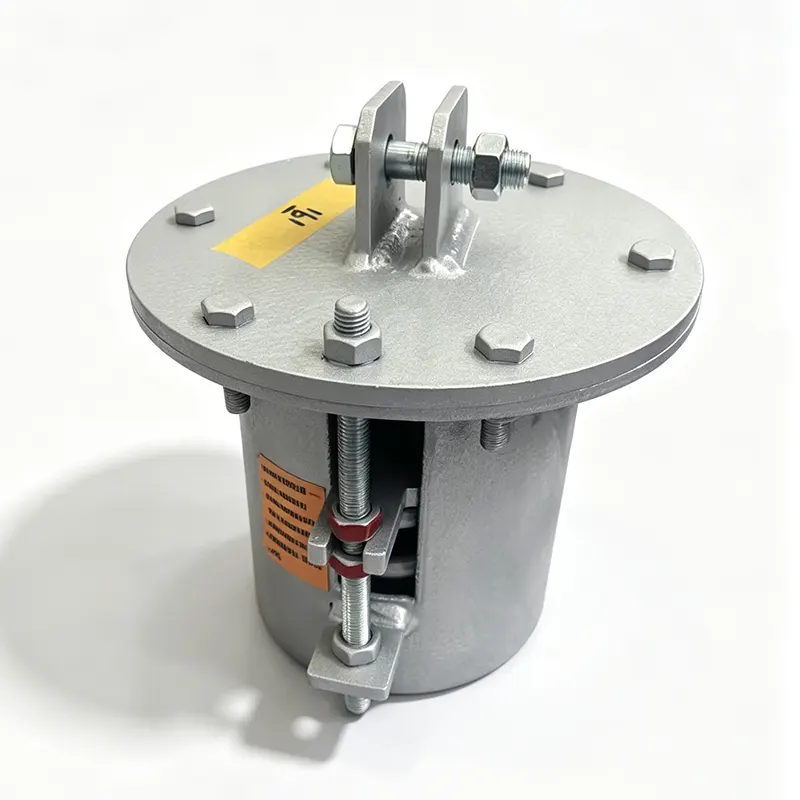
Shock Absorbing Pipe Support
In modern process plants, power stations, and offshore platforms, piping systems are rarely static. Pumps, compressors, relief valves, and fast-acting isolation valves generate hydraulic transients and mechanical pulses that travel through the pipe wall. If these dynamic loads are not controlled, they concentrate stress at elbows, tees, and welded attachments, leading to fatigue cracking, flange leaks, and premature support failure. A Shock Absorbing Pipe Support is designed specifically to absorb this transient energy and keep the pipe within its allowable stress range. While a Pipe Support for Low Temperature addresses brittle fracture risks in cryogenic lines, and a Seismic Pipe Support is sized for lateral and longitudinal movement during an earthquake, the shock absorbing unit focuses on short-duration, high-energy events. It works together with an Anti Vibration Pipe Support to cover both steady-state vibration and impulse loading, and it can be installed alongside a Pipe Support with PTFE Plate when the same line needs low-friction sliding during thermal expansion. Selecting the right combination of these supports reduces total installed stress, protects rotating equipment nozzles, and lowers maintenance costs over the life of the plant. Typical applications include boiler feedwater lines, reciprocating compressor discharge headers, firewater deluge systems, and long transfer lines where valve closure can generate pressure surges exceeding 20 bar. Without adequate damping, these surges can exceed the pipe’s fatigue endurance limit within a few thousand cycles. By adding a shock absorbing support at calculated node points, engineers can reduce peak dynamic displacement by up to 70% compared with a rigid strut.
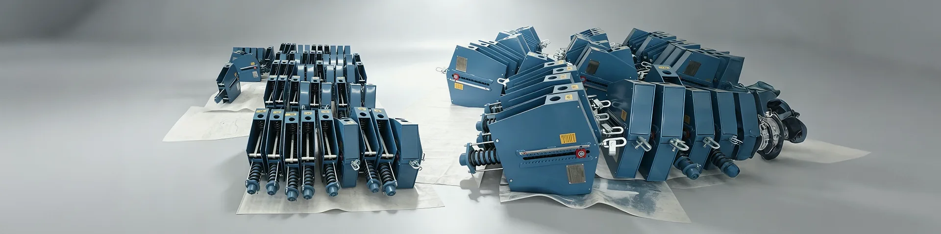
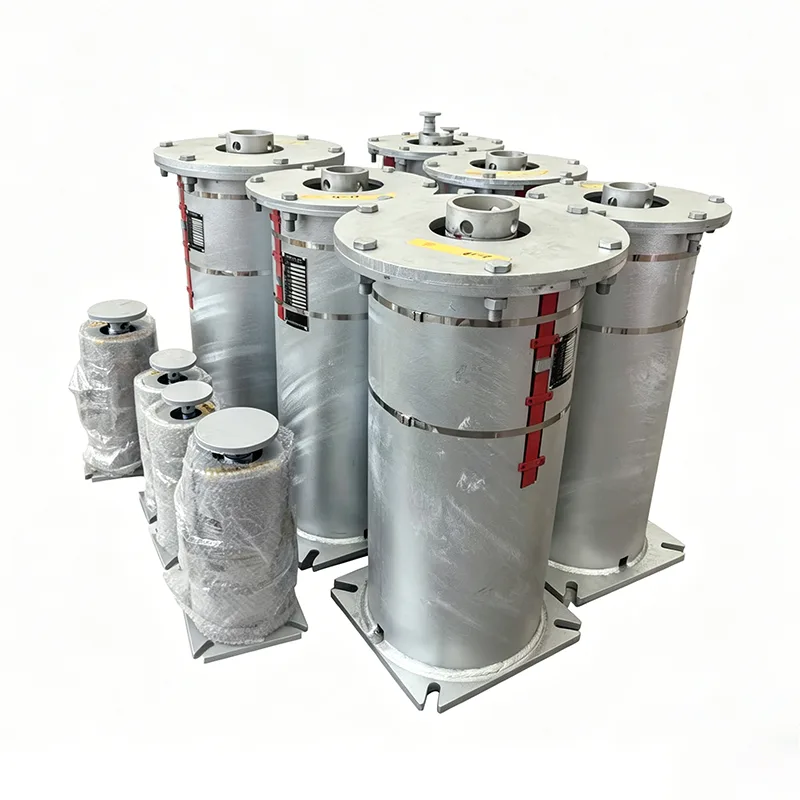
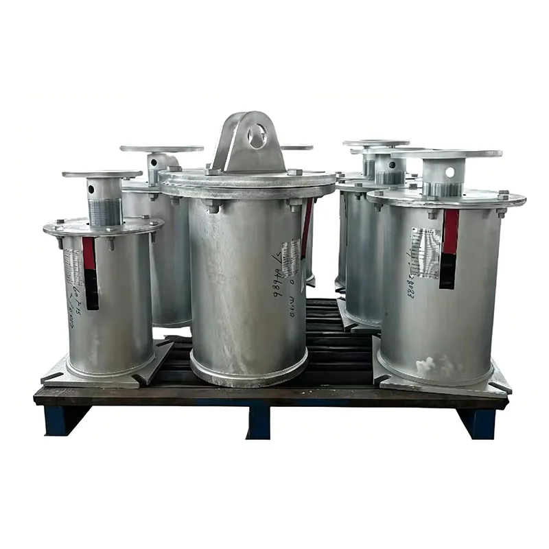
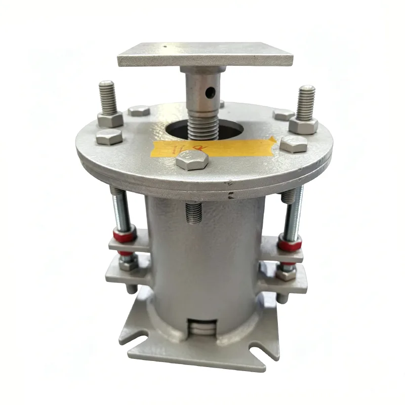
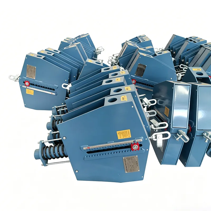
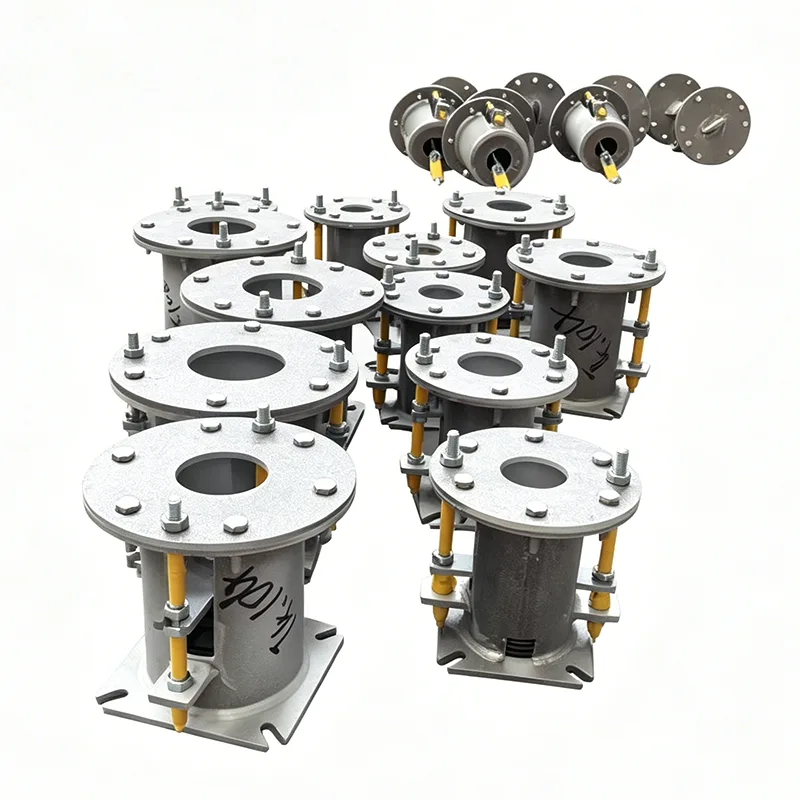
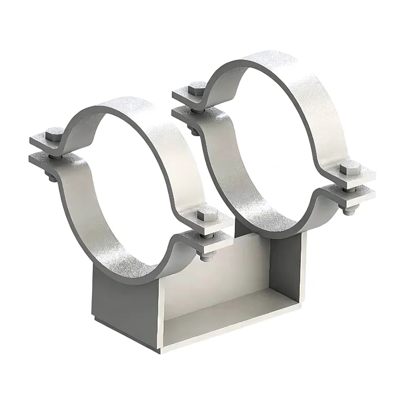
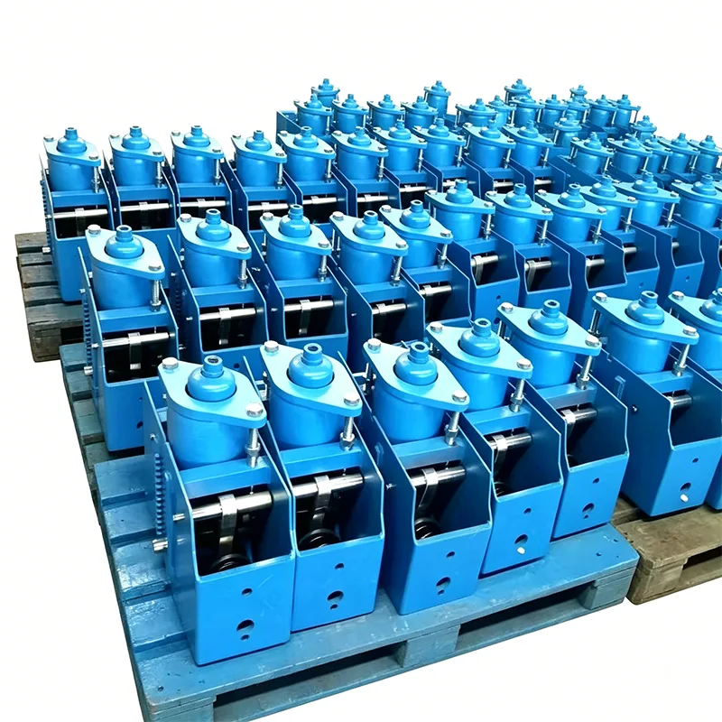
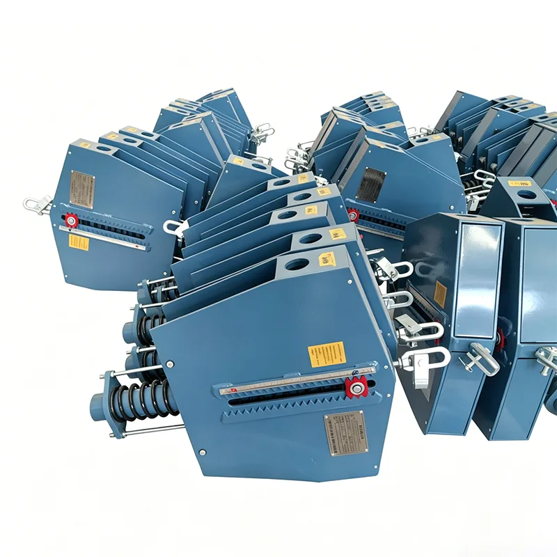
The Shock Absorbing Pipe Support uses a pre-compressed helical spring in parallel with a hydraulic damping element. The spring is sized to carry the static load while the damper resists velocity, meaning that under slow thermal movement the support offers minimal resistance, but under a sudden shock it locks up and dissipates energy. This velocity-dependent behavior is critical for lines that must move during startup and shutdown but still need protection from water hammer and steam hammer. The unit is supplied with a calibrated load indicator, a locking collar for preset adjustment, and an anti-rotation bracket for overhead mounting. The standard housing is fabricated from S235JR carbon steel and finished with hot-dip galvanizing to ISO 1461. For chemical or offshore service, the housing, rod, and fasteners can be upgraded to AISI 316L stainless steel. The sealing system uses a double-lip nitrile wiper and a PTFE guide ring, with an optional graphite packing for high-temperature steam lines. Every unit is load-tested at the factory before shipment. The damping curve is verified at three stroke velocities to ensure consistent performance across the operating range. Standard compliance includes ASME B31.1 and B31.3 for power and process piping, and the support can be supplied with EN 10204 3.1 material certificates. Installation requires only a standard pipe clamp and a single structural attachment point, which simplifies retrofits in congested pipe racks. The support is maintenance-free for the first 10,000 operating hours, after which the damping fluid can be replaced through a sealed port. For applications with continuous high-frequency vibration, a lockable version is available that limits piston movement to ±3 mm to protect sensitive instrumentation. The product is available in six standard frame sizes, with each size covering a specific load band. The table below lists the nominal load range, maximum stroke, and physical dimensions for the standard catalog range. Custom models with higher capacity, longer stroke, or special corrosion allowance can be engineered for project-specific requirements. When specifying a Shock Absorbing Pipe Support, the dynamic load, pipe movement direction, and available structural clearance should be provided to ensure the correct spring preload and damping rate are selected.
- Maximum shock load capacity: 5 kN to 350 kN
- Allowable vibration amplitude: ±2 mm to ±25 mm
- Working temperature range: -40°C to +200°C with standard nitrile seals; -196°C to +350°C with optional PTFE/metal seals
- Damping ratio: 0.15 to 0.35 depending on stroke position
- Spring preload adjustment: 0% to 40% of rated capacity
- Surface protection: hot-dip galvanized, epoxy paint, or stainless steel
| Model | Load Range | Stroke | Overall Height | Weight |
|---|
| SAPS-05 | 5–18 kN | 50 mm | 210 mm | 4.2 kg |
| SAPS-25 | 18–45 kN | 75 mm | 260 mm | 8.5 kg |
| SAPS-80 | 45–90 kN | 100 mm | 320 mm | 16.3 kg |
| SAPS-150 | 90–160 kN | 125 mm | 380 mm | 27.8 kg |
| SAPS-250 | 160–250 kN | 150 mm | 440 mm | 41.6 kg |
| SAPS-350 | 250–350 kN | 175 mm | 500 mm | 58.2 kg |