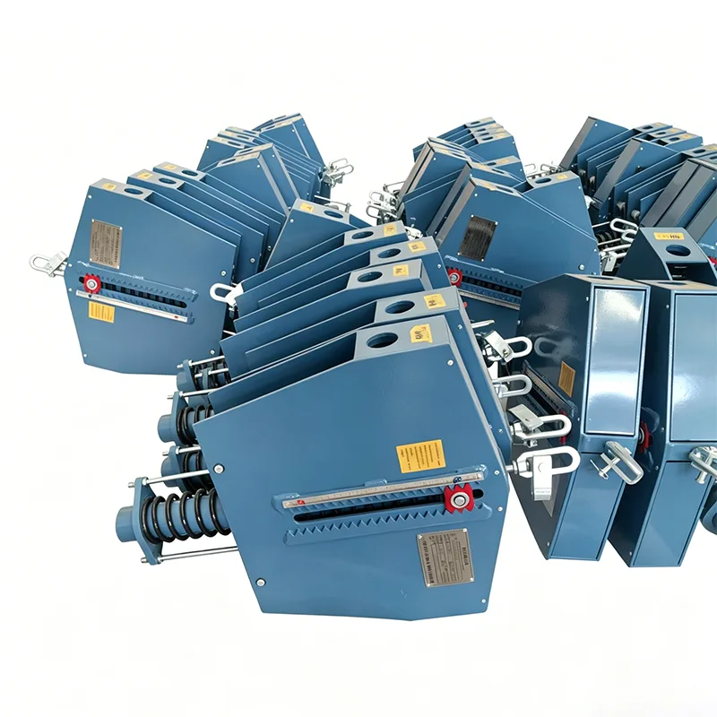
Refinery Spring Hanger
In refinery piping networks, thermal expansion and contraction impose variable vertical loads on critical lines such as heater transfer lines, column overheads, and hot reboiler circuits. A Refinery Spring Hanger is designed to carry these changing loads while permitting the predetermined movement calculated in the piping stress analysis. Unlike rigid supports, the spring mechanism maintains near-constant load across the full travel range, reducing stress at nozzle connections and preventing excessive sag. For comparable high-temperature applications in downstream processing and steam generation, the Petrochemical Spring Hanger and the Thermal Power Spring Hanger use the same load-calibrated spring principle, making them suitable reference points for integrated plant support systems where coordinates and load ratings must match across battery limit interfaces.
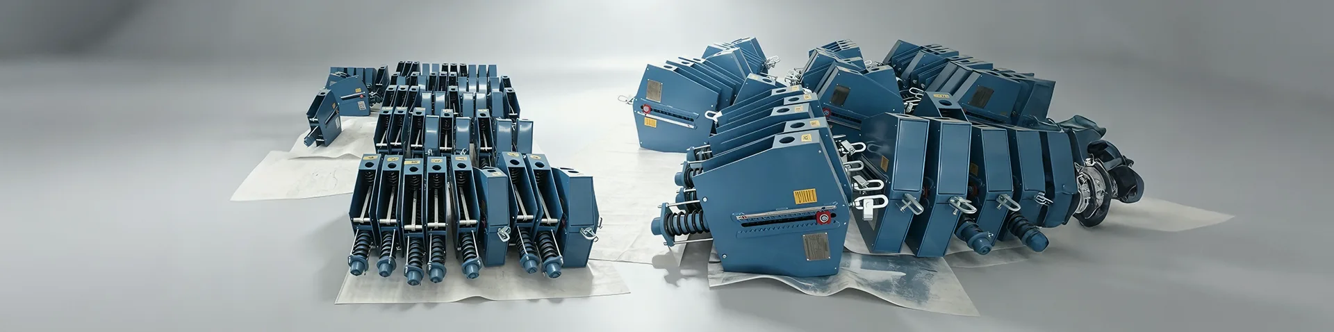
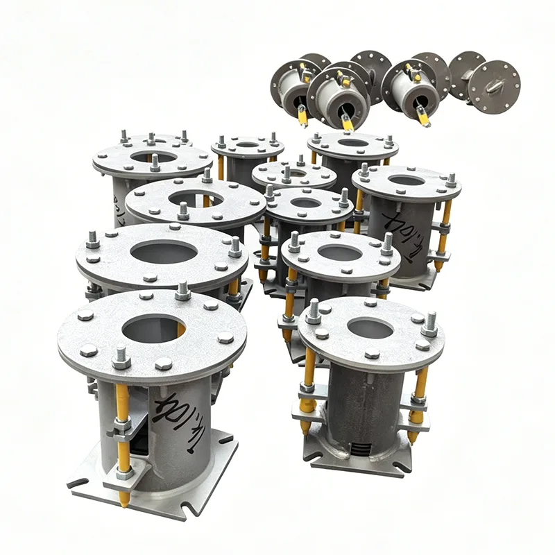
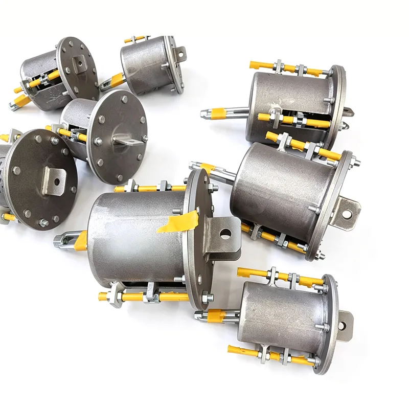
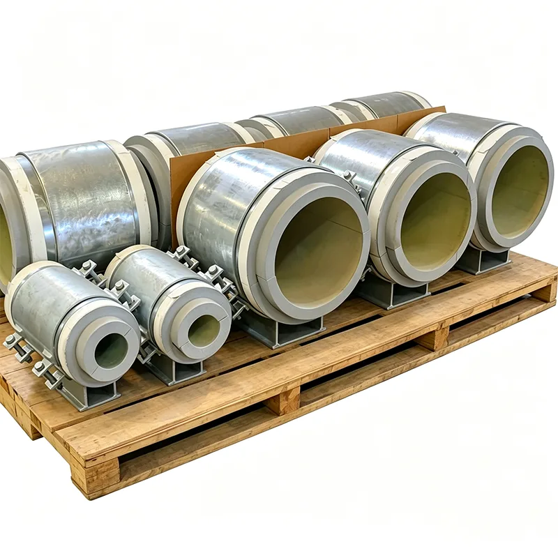
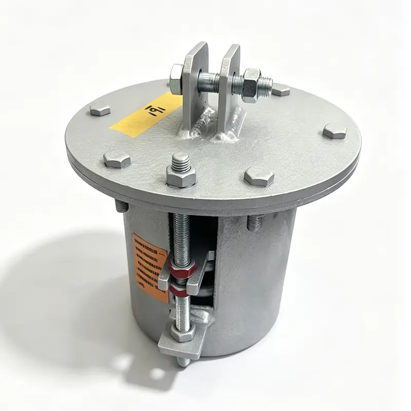
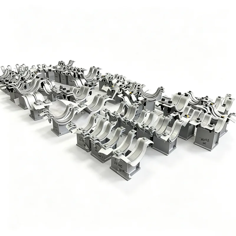
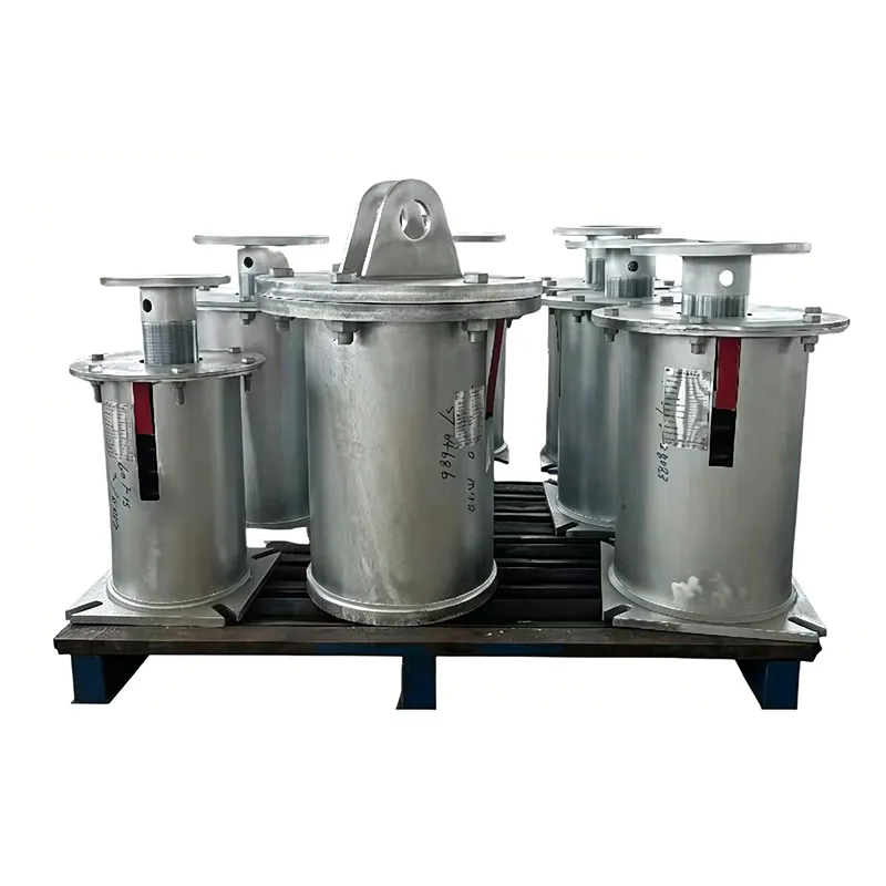
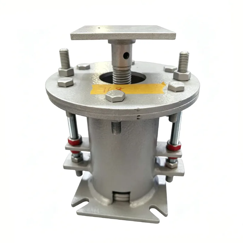
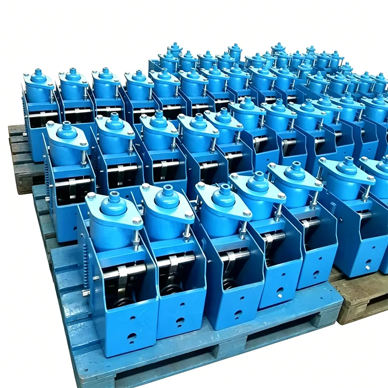
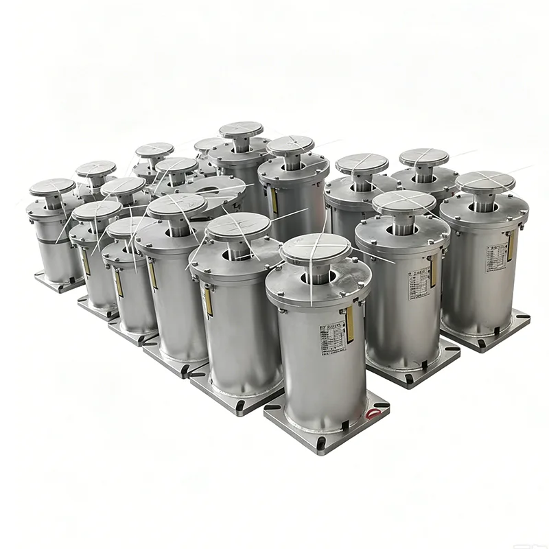
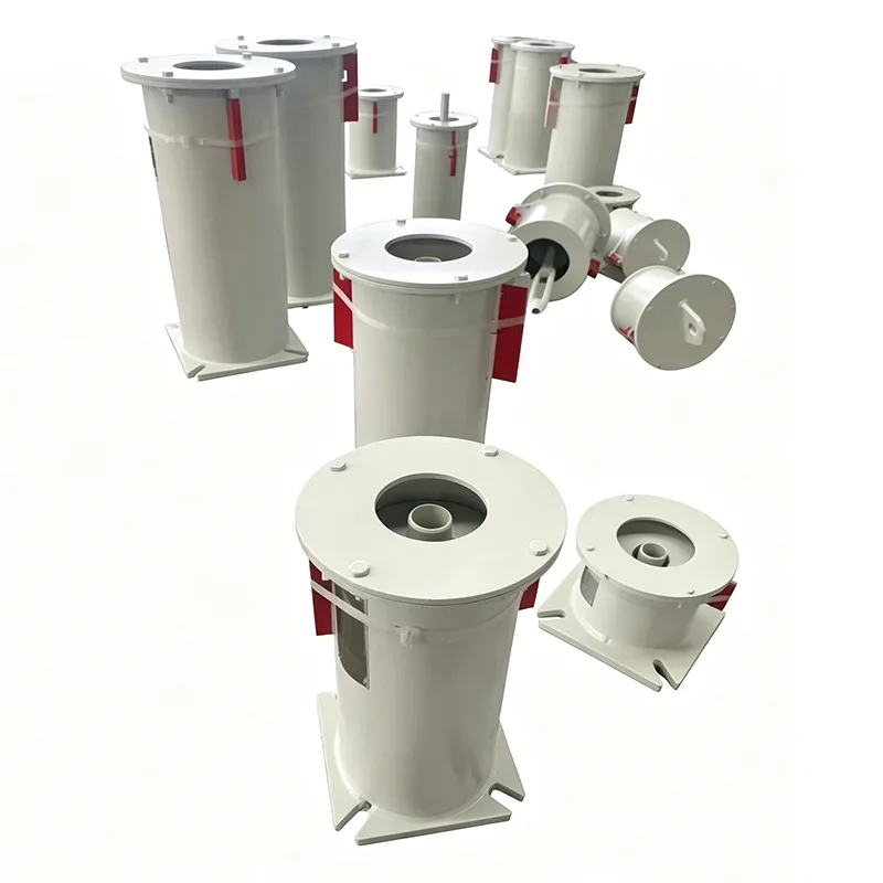
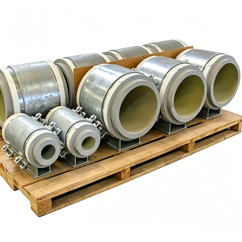
Refinery Spring Hanger assemblies are manufactured with a heavy-duty casing that protects the spring coil from external damage, dust, and hydrocarbon vapors. Each unit is calibrated to the specified hot load, cold load, and travel range before leaving the workshop. The load adjustment mechanism allows field technicians to fine-tune the support force after hydrostatic testing or during startup. High-strength threaded hanger rods, turnbuckles, and locking pins are supplied as part of the assembly to simplify installation and prevent accidental release of stored energy. For corrosive refinery environments, all load-bearing components can be fabricated from stainless steel or alloy steel with PTFE slide plates and hot-dip galvanized finishes. Units are marked with load, travel, and serial number for traceability, and they can be configured for base plate mounting, beam attachment, or riser clamp connections depending on the pipe routing geometry.
Key Technical Parameters
- Load capacity range: 1 kN to 320 kN (225 lbf to 71,940 lbf) in standard series
- Total vertical travel: 25 mm to 400 mm (0.98 in to 15.75 in)
- Spring type: variable effort helical coil, option for constant support hanger
- Shell material: ASTM A36 carbon steel, AISI 304, AISI 316 stainless steel
- Spring material: alloy spring steel, shot-peened and preset to prevent relaxation
- Surface treatment: hot-dip galvanized, epoxy painted, or zinc-nickel coated
- Design standards: MSS SP-58, MSS SP-69, ASME B31.3, and NACE MR0175 for sour service
- Operating temperature: -46°C to 480°C (-50.8°F to 896°F) for metal components
- Overload protection: 150% rated load without permanent set
- Blocking devices: travel stops and load pins for hydrotest and shipping
- Hot load tolerance: ±5% of specified value after spring calibration
- Certification: material test certificates, load-deflection curves, and NDE on request
Standard Model Selection
| Model | Load Capacity | Max Travel | Shell Material | Spring Material | Finish | Temp. Range |
|---|
| RSH-01 | 1 – 6 kN | 50 mm | Carbon Steel | Alloy Spring Steel | Epoxy | -20°C to 200°C |
| RSH-02 | 6 – 18 kN | 100 mm | Carbon Steel / SS304 | Alloy Spring Steel | HDG | -40°C to 300°C |
| RSH-03 | 18 – 45 kN | 150 mm | Stainless Steel 304 | Stainless Spring | Epoxy | -46°C to 400°C |
| RSH-04 | 45 – 90 kN | 200 mm | Stainless Steel 316 | Alloy / Inconel | Zinc-Nickel | -46°C to 450°C |
| RSH-05 | 90 – 160 kN | 300 mm | Stainless Steel 316 | Alloy / Inconel | Epoxy | -46°C to 480°C |
| RSH-06 | 160 – 320 kN | 400 mm | Alloy Steel | Alloy Spring Steel | HDG | -46°C to 480°C |
Selecting the correct Refinery Spring Hanger begins with the piping stress report, which defines hot load, cold load, and vertical displacement at each support point. The spring hanger is then sized so that the load variation remains within the allowable range from cold to hot position. For lines with stringent load limits at rotating equipment nozzles, a constant support spring hanger may be specified instead of a variable effort unit. Installation should follow the marked load and travel values, with the travel stop removed only after the line is fully filled and brought to operating temperature. Regular inspection of the spring coil and load indicator confirms that the support has not drifted beyond its calibrated envelope and allows maintenance teams to plan replacement without unplanned shutdowns.
Ordering Data Checklist
- Pipe size and insulation thickness
- Hot load and cold load values
- Required vertical movement and direction
- Support type: variable effort or constant support
- Shell and internal material requirements
- Protective coating specification
- Connection details: base plate, beam clamp, or welded lug
- Design code and project specification number