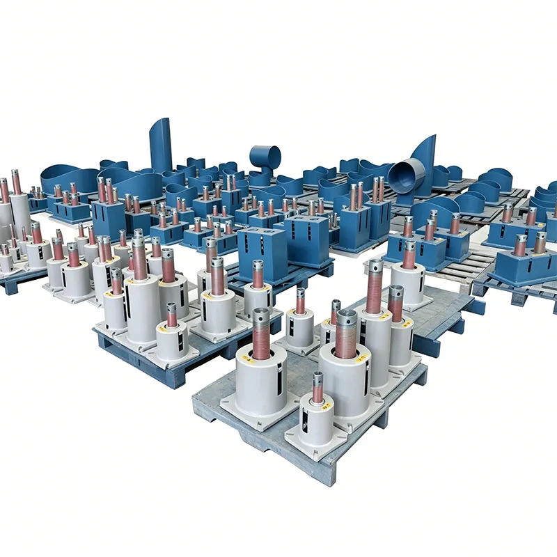
Thermal Power Spring Hanger
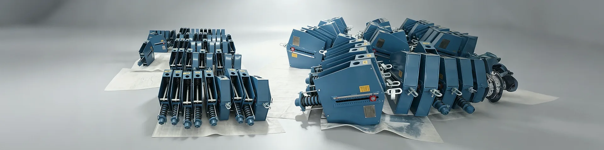
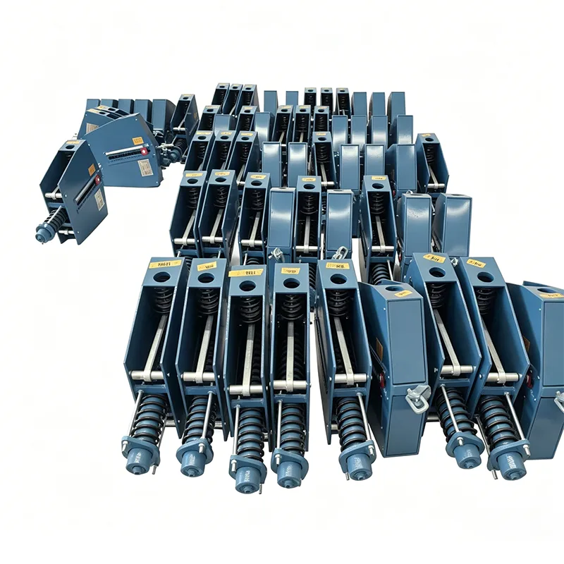
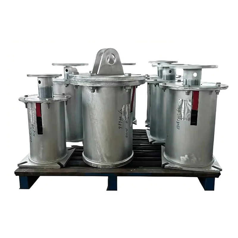
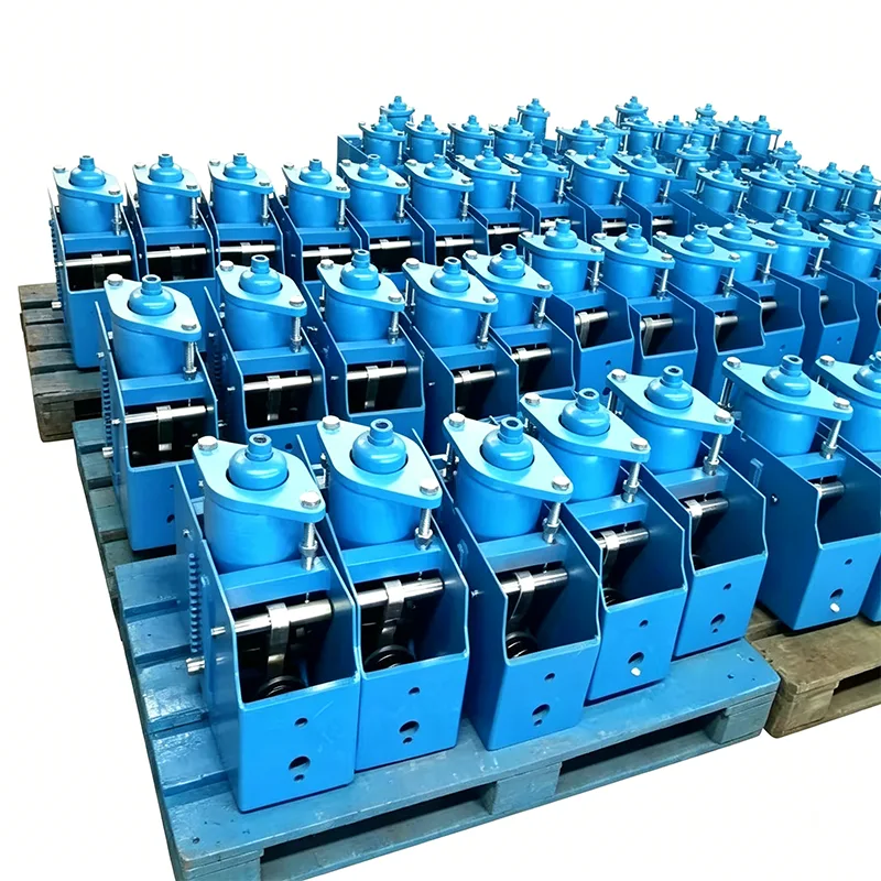
In thermal power generation facilities, piping systems must cope with severe thermal expansion, vibration, and fluctuating loads during start-up and shut-down cycles. A Thermal Power Spring Hanger is engineered to provide reliable vertical support while compensating for pipe movement without transferring excessive stress to boilers, turbines, feedwater heaters, or condensate lines. The assembly is pre-set to the calculated cold load and locked with a travel pin, ensuring safe erection and alignment before system operation. In addition to steady-state weight carrying, the unit must withstand occasional seismic loads and water hammer events commonly found in main steam and hot reheat piping. For similar high-temperature service in adjacent industries, our product line includes the Refinery Spring Hanger, configured for fired heaters and transfer lines in refineries, and the Petrochemical Spring Hanger, built for ethylene crackers and chemical reactor piping. All models share the same modular housing design, calibrated spring coils, and field-adjustable load settings to minimize installation time and improve operational safety.
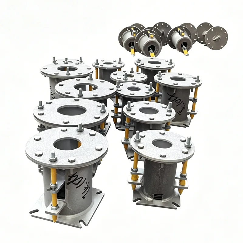
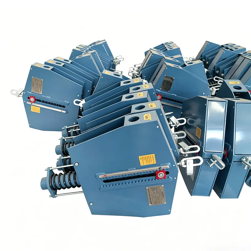
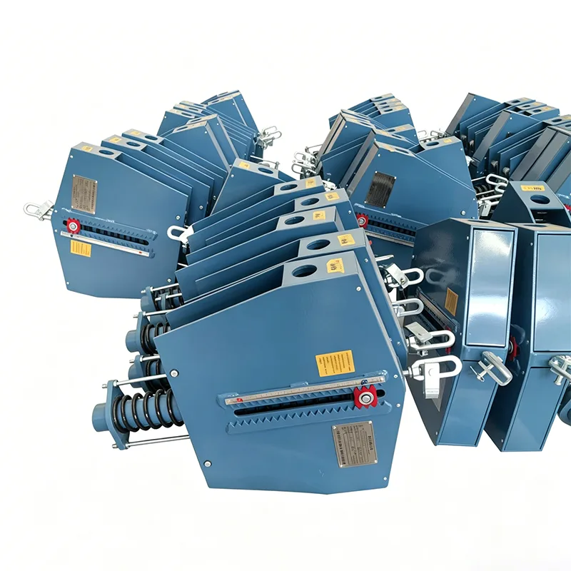
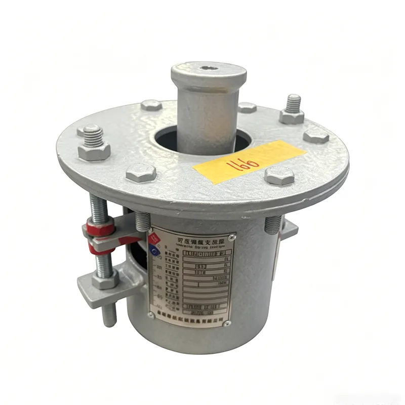
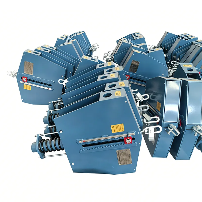
The Thermal Power Spring Hanger combines a robust variable or constant support mechanism with materials selected for long-term exposure to high-temperature steam, flue gas, and fly ash. Spring coils are shot-peened and preset to a tolerance of ±5% of the design load, then individually load-tested on a calibrated test stand. The housing is available in carbon steel with hot-dip galvanizing or high-solids epoxy coating, or in stainless steel 304/316 for corrosive environments. Travel stops and locking pins are color-coded to simplify field removal after hydrostatic testing. The compact swing-bolt connection allows quick attachment to beam clamps, welded lugs, or pipe stanchions, while the load indicator plate provides a direct reading of cold and hot positions. The load adjustment mechanism uses a threaded turnbuckle or compression nut, enabling fine tuning without removing the hanger from service. Multiple spring coils can be nested within a single housing to increase load capacity while keeping the profile compact. All components are traceable by heat number, and the nameplate is laser-etched to resist fading from fly ash or steam leaks. For pulverized coal and combined cycle plants with frequent thermal cycling, constant support models maintain a nearly uniform load throughout the full travel range, reducing the risk of overstressing welds and branch connections.
Standard Product Parameters
- Type: variable spring hanger, constant spring hanger, or dual-spring backup configuration
- Load capacity: 500 N to 500 kN standard; higher loads available with multiple hanger frames
- Allowable vertical travel: 25 mm to 300 mm in standard increments of 25 mm
- Load variation: less than 5% for constant spring models across full travel
- Design code: MSS SP-58, MSS SP-69, ASME B31.1, and EN 13480 for power plant piping
- Spring material: chrome vanadium, chrome silicon, 17-7 PH stainless steel, or Inconel X-750
- Housing material: ASTM A36, A572 Grade 50, AISI 304, AISI 316, or duplex stainless steel
- Surface protection: hot-dip galvanized per ASTM A123, epoxy powder coat 150–250 µm, or zinc-nickel plating
- Operating temperature: -40°F to 1,200°F (-40°C to 650°C) depending on trim and coating
- Preset load verification: calibrated hydraulic load cell with digital readout, certificate included
- Options: travel stops, limit switches, anti-vibration dampers, and custom paint systems
- Marking: stainless steel nameplate with tag number, load, travel, and cold/hot positions
Model Selection Table
Common Thermal Power Spring Hanger configurations
| Model | Type | Load Range (kN) | Travel Range (mm) | Housing Material | Spring Material |
|---|
| TP-SH-V01 | Variable | 0.5 – 25 | 25 – 75 | Carbon steel, epoxy coated | Chrome vanadium alloy |
| TP-SH-V02 | Variable | 25 – 100 | 50 – 150 | Carbon steel, HDG | Chrome silicon alloy |
| TP-SH-V03 | Variable | 100 – 250 | 75 – 200 | A572 Grade 50, HDG | Chrome silicon alloy |
| TP-SH-C01 | Constant | 10 – 80 | 50 – 200 | Stainless steel 304 | Inconel X-750 |
| TP-SH-C02 | Constant | 80 – 300 | 100 – 300 | Stainless steel 316 | 17-7 PH stainless |
| TP-SH-C03 | Constant | 300 – 500 | 150 – 300 | Duplex stainless steel | Inconel X-750 |
Materials and Surface Protection
- Carbon steel housings: ASTM A36 or A572 Grade 50 with hot-dip galvanizing per ASTM A123, minimum coating thickness 86 µm for 6 mm base metal, or epoxy powder coat 150–250 µm
- Stainless steel housings: AISI 304/316 for chloride-bearing or coastal environments; passivated and pickled finish as standard
- Spring coils: chrome vanadium for general service up to 400°F, chrome silicon for up to 500°F, 17-7 PH stainless for corrosive service, and Inconel X-750 for continuous operation up to 1,200°F
- Fasteners: ASTM A193 B7 or B8 with matching nuts and washers; available with PTFE coating for ease of adjustment
- Load flanges and turnbuckles: forged alloy steel, proof-tested to 1.5 times rated load
Factory Testing and Documentation
- Each spring hanger is tested at cold and hot positions using a calibrated load cell with digital readout accuracy of ±0.5%
- Test certificate includes serial number, tag number, preset load, travel, and spring rate
- Material traceability per EN 10204 3.1 or 3.2 available upon request
- Third-party inspection by TÜV, SGS, or Bureau Veritas can be arranged before shipment
Installation and Adjustment Notes
- Keep the shipping pin installed until piping hydrostatic test is complete and insulation is applied
- Verify that actual cold position matches the preset marking on the load indicator plate; if not, adjust turnbuckle in quarter-turn increments
- Do not exceed the maximum travel shown on the nameplate; select the next travel range if pipe movement exceeds 90% of rated travel
- For constant support models, the load should remain within ±5% of design from cold to hot position; field re-verification is recommended after first thermal cycle
- Inspect spring coils for corrosion or cracks every 12 months in high-temperature service; replace if surface pitting exceeds 0.5 mm depth